Metal Prototyping
The
special of metal prototyping need that motivates the
variety of rapid prototyping technologies arises because product designers
would like to have a physical model of a new part or product design rather than
a computer model or line drawing. The creation of a prototype is an integral
step in the design procedure.
Available
rapid prototyping technologies for metal prototyping can be divided into two
basic categories:
(1)
Material removal processes.
(2)
Material addition processes.
The
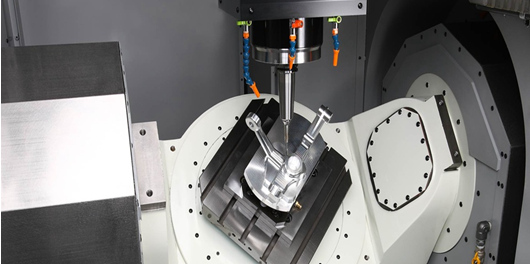
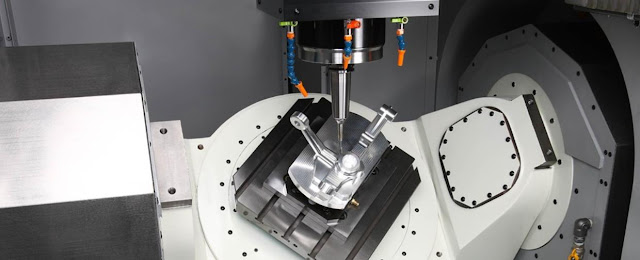
material removal RP alternative involves machining, primarily milling and
drilling, using a dedicated Computer Numerical Control (CNC) machine that is
available to the design department on short notice. To use CNC, a part program
must be prepared from the CAD model The starting material is often a solid
block of wax, which is very easy to machine, and the part and chips can be
melted and resolidified for reuse when the current prototype is no longer
needed. Other starting materials can also be used, such as wood, or metals (a
machinable grade of aluminum or brass). The CNC machines used for rapid
prototyping are often small, and the terms desktop milling or desktop machining
are sometimes used for this technology .Maximum starting block sizes in desktop
machining are typically 180 mm (7 in) in the x-direction, 150 mm (6 in) in the
y-direction and 150 mm (6 in) in the z-direction.
The
principal emphasis is on material addition RP technologies, all of which work
by including layers of material each one in turn to manufacture the strong part
from base to top.
Metal prototyping Technologies
1- 3D printing
2-
Sand casting
3-
Fabricating metal prototypes
4-
Machining metal prototypes
1- 3D printing
Droplet Deposition
Manufacturing (DDM)
These systems operate by melting the starting material and shooting
small droplets onto a previously formed layer. The liquid droplets coldweld to
the surface to form a new layer. The deposition of droplets for each new layer
is controlled by a moving -spray nozzle work head whose path is based on a
cross section of a CAD geometric model that has been sliced into layers
(similar to the other RP systems described in the preceding).After each layer
has been applied, the platform supporting the part is lowered a certain
distance corresponding to the layer thickness, in preparation for the next
layer.
An important criterion that must be satisfied by the starting
material is that it be readily melted and solidified. Work materials used in
DDM include wax and thermoplastics. Metals with low melting point, such as tin,
zinc, lead, and aluminum, have also been tested
-Selective laser
sintering (SLS)
Another way for metal prototyping uses a moving laser beam to
sinter heat-fusible powders in areas corresponding to the CAD geometric model
one layer at a time to build the solid part. After each layer is completed, a
new layer of loose powders is spread across the surface using a
counter-rotating roller. The powders are preheated to just below their melting
point to facilitate bonding and reduce distortion. Layer by layer, the powders
are gradually bonded into a solid mass that forms the three-dimensional part
geometry. In areas not sintered by the laser beam, the powders remain loose so
they can be poured out of the completed part. Meanwhile, they serve to support
the solid regions of the part as fabrication proceeds Metal and ceramic powders
are being used in SLS.
2- Sand casting
Sand casting is by far the most important casting process. A sand casting mold
will be used to metal prototyping. The mold
composed of two halves the cope and the drag. The cope is the top half of the
mold, and the drag is the bed half. These two mold parts are contained in a
box, called a flask, which is also divided into two halves, one for the cope
and the other for the drag. The two halves of the mold separate at the line. In
sand casting (and other expendable-mold processes), the mold cavity is formed
by means of a pattern, which is made of wood, metal, plastic, or other material
and has the shape of the part to be cast. The hole is shaped by pressing sand
around the example, about a large portion of each in the adapt and drag, so
that when the pattern is removed, the remaining void has the desired shape of
the cast part. The pattern is usually made oversized to allow for shrinkage of
the metal as it solidifies and cools.
3- Fabricating metal prototypes
Fabricating
metal prototypes embrace sheets, rods, tubing, bars, and wire. Any of those are
often used because the raw materials to fabricate a metal image as a downstream
secondary step, instead of through primary producing like casting or 3D
printing.
For sheet image producing, many alternative processes are often utilized to fabricate an image. As an example, the physical model can be two-dimensional and arranged out on the metal sheet to use it as a model, then lasers or torches can be wont to slice outlines and openings, and to mark bends. Presses can be wont to bend the metal at the marked boundaries, and specialized attachment instrumentality is often wont to be part of components along. employees weld image automotive fabrications speedy prototyping by attachment fabrications permits for minor changes to be created to samples while not important time and value conduit are often used for prototyping by a process it through a variety of various operations to form an image half that matches the design:
Flaring, Swaging, Dimpling, Bending, Flattening, and Piercing.
Expanding the most advantage of fabricating a mental image is that the time potency. Patterns or molds don't seem to be required, and therefore the raw materials are on the market off the shelf. The disadvantage is that some image styles are too advanced for normal producing processes and so cannot be created with this method.
4- Machining metal prototypes
Machining
is any method wherever a bit of material removes a desired final form and size
by a controlled material removal method additionally called reductive
producing. It may be wont to manufacture varied metal merchandise, yet as
materials like wood, plastic, ceramic, and composites. In trendy production,
machining is administered by computer numerical control (CNC).
CNC
is that the processed management of machining instrumentality to create a
region in step with a 3D model. Machining instrumentality embraces lathes,
mills, routers, drills, and grinders. The material for CNC machines is stock
metal merchandise like steel plates and bars.


Comments
Post a Comment